4 Bit Synchronous Counter Design Using Jk Flip-flop
The synchronous counter counts the number of clock pulses received at its input. Generally, it is constructed using either JK flip flops or T flip flops.
Before learning the design of the synchronous counter, you can go through the construction, operation and timing diagram of the synchronous counter.
Design steps of synchronous counter
- Find the number of flip flops using 2n ≥ N, where N is the number of states and n is the number of flip flops.
- Choose the type of flip flop.
- Draw the state diagram of the counter.
- Draw the excitation table of the selected flip flop and determine the excitation table for the counter.
- Use K-map to derive the flip flop input functions.
Design Problem #1
Design 3-bit synchronous up counter using JK flip flops.
Step 1: Find the number of flip flops.
A flip flop stores only one bit, hence for a 3 bit counter, 3 flip flops(n=3) are needed to design the counter.
Number of states = 2n = 23 = 8 states(000, 001, 010, 011, 100, 101, 110, 111)
Step 2: Choose the type of flip flop.
Since the type of flip flop is given in the problem, let us use JK flip flops.
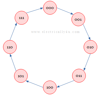
Step 3: Draw state diagram for the counter .
The state diagram for the counter is drawn as below.
Step 4: Obtain excitation table for the counter.
We know, the excitation table for JK flip flop is given by,
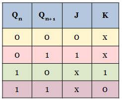
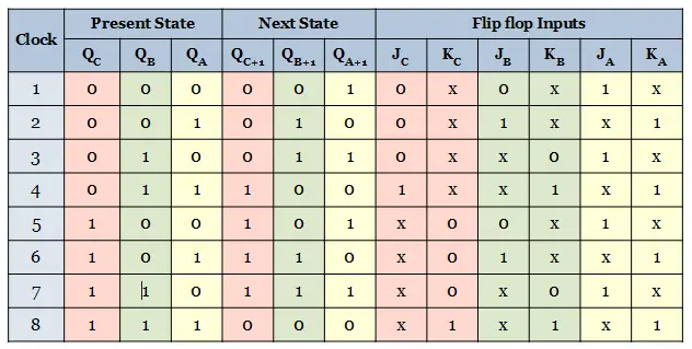
Now the excitation table for the 3-bit synchronous counter is determined from the excitation table of JK flip flop.
The excitation table is framed for 8 states of the counter. Since 3 flip-flops are used in the design, the present state, next state and flip flop inputs for each flip flop are considered.
Step 5: Derive the flip flop input functions .
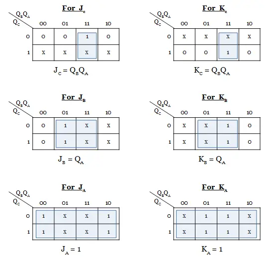
Using Karnaugh maps, the input functions for the 3 flip flops are derived. The present states are the input for all the flip-flops. Since there are three inputs(QC, QB, QA), 8 cell K-map is used.
Learn the minimization of boolean expression using K-map.
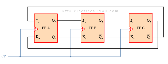
Step 6: Draw the logic diagram of the counter.
The logic diagram of the 3-bit synchronous counter is drawn as follows. Draw the 3 JK flip-flops. The common clock input is given to all the flip-flops. The inputs for each flip-flop are drawn as per the logic functions derived in the previous step.
Design Problem #2
Design a Mod-6 synchronous up Counter.
Step 1: Find the number of flip flops.
Mod-6 counter represents that the counter will have 6 states. Thus, N =6.
The number of flip-flops used for counter design is determined using the formula, 2 n ≥ N.
By trial and error method, the value of n is found to be 3. That is the number of flip-flops, n = 3.
Hence the 6 counter states are 000, 001, 010, 011, 100, 101.
Step 2: Choose the type of flip flop.
Let us choose the JK- flip flop to design the Mod-6 synchronous up counter.
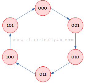
Step 3: Draw state diagram for the counter .
The state diagram for the mod-6 counter with 6 states is drawn as below.
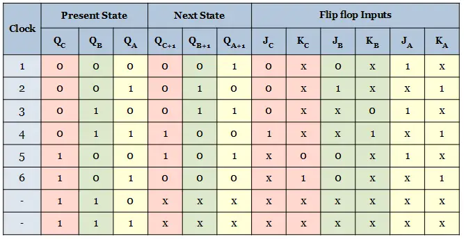
Step 4: Obtain an excitation table for the counter.
The excitation table for JK flip flop is given by,
Now the excitation table for the mod-6 synchronous counter is determined from the excitation table of JK flip flop.
The excitation table is framed for 6 states of the counter. Since 3 flip-flops are used in the design, the present state, next state and flip flop inputs for each flip flop are considered.
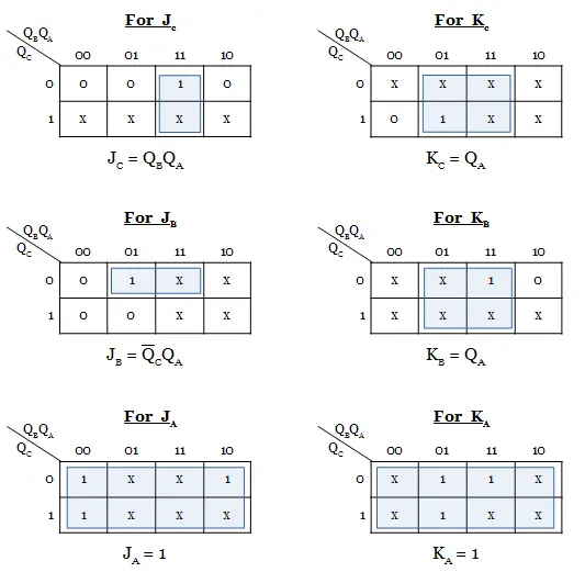
Step 5: Derive the flip flop input functions .
Using K-maps, the input functions for the 3 flip flops are derived. The present states are the input for all the flip-flops. Since there are three inputs(QC, QB, QA), 8 cell K-map is used.
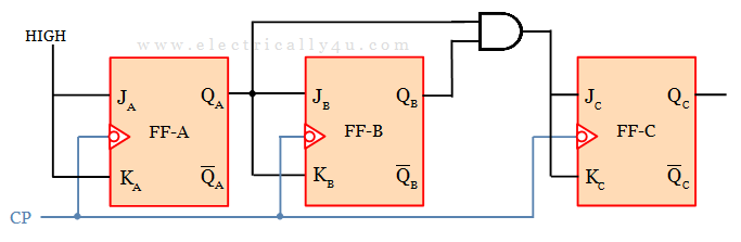
Step 6: Draw the logic diagram of the counter.
The logic diagram of the mod-6 synchronous up counter is drawn as follows. Draw the 3 JK flip-flops. The inputs for each flip-flop are drawn as per the logic functions derived in the previous step.
Design Problem #3
Design a synchronous counter with count sequnce: 000, 001, 011, 111, 110, 100, 000,…
Step 1: Find the number of flip flops.
The given count sequence has 3 bits and there are 6 seven states.
Hence the counter to be designed will have 3 flip-flops.
Step 2: Choose the type of flip flop.
Let us choose JK flip-flops to design the counter.
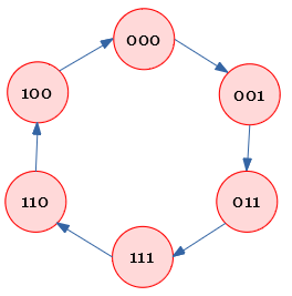
Step 3: Draw state diagram for the counter .
The state diagram for the given count sequence is drawn as below.
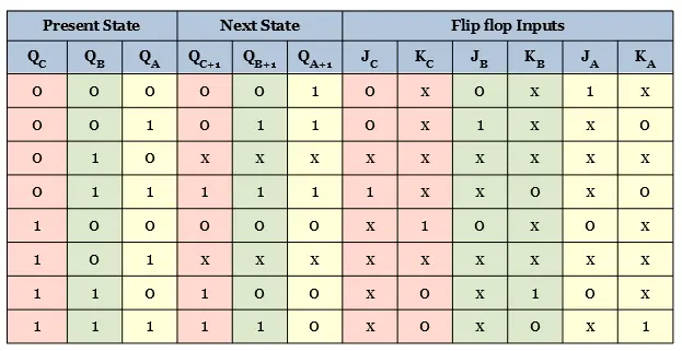
Step 4: Obtain an excitation table for the counter.
The excitation table for the synchronous counter is determined from the excitation table of JK flip flop.
The excitation table is framed for 6 states of the counter. Since 3 flip-flops are used in the design, the present state, next state and flip flop inputs for each flip flop are considered.
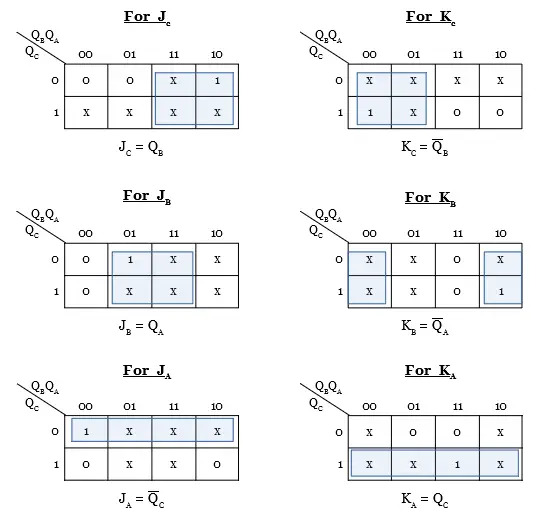
Step 5: Derive the flip flop input functions .
Using K-maps, the input functions for the 3 flip flops are derived. The present states are the input for all the flip-flops. Since there are three inputs(QC, QB, QA), 8 cell K-map is used.
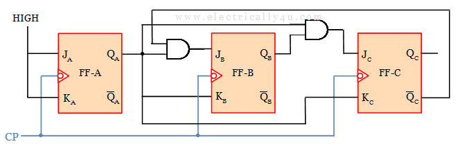
Step 6: Draw the logic diagram of the counter.
The logic diagram of the synchronous up counter or the given count sequence is drawn as follows. Draw the 3 JK flip-flops. The inputs for each flip-flop are drawn as per the logic functions derived in the previous step.

An Assistant Professor in the Department of Electrical and Electronics Engineering, Photoshop designer, a blogger and Founder of Electrically4u.
4 Bit Synchronous Counter Design Using Jk Flip-flop
Source: https://www.electrically4u.com/design-of-synchronous-counter/
0 Response to "4 Bit Synchronous Counter Design Using Jk Flip-flop"
Post a Comment